We have seen that sampling a bandlimited signal at or above the Nyquist sampling rate does
not destroy any information content and fully characterises the bandlimited signal. A
system transmitting these sampled values of the bandlimited signal is called a sampled-
data or pulse modulation system. In modern communication systems, these sampled
signals are often quantised and coded before transmission. We have pulse code
modulation (PCM).
Pulse code modulation is very popular because of the many advantages it offers. These
include:
1. Inexpensive digital circuitry may be used in the system.
2. All-digital transmission. PCM signals derived from analogue signals may be time-
division multiplexed with data from digital computers and transmitted over a
common high-speed channel.
3. Further digital signal processing such as encryption is possible.
4. Errors may be minimised by appropriate coding of the signals.
5. Signals may be regularly reshaped or regenerated using repeaters at appropriate
intervals.
Figure 14.1 shows a single-channel PCM system.
Figure 14.1 A single-channel PCM transmission system.
An analogue message m(t) is first sampled at or above the Nyquist sampling rate. These
sampled signals are then converted into a finite number of discrete amplitude levels. The
conversion process is called quantisation. Figure 14.2 shows how an analogue message
is converted into 8 amplitude levels with equal spacing by an 8-level quantiser.
Figure 14.2 Message and quantised signal.
Quantisation obviously reduces the degree of accuracy of representation of the sampled
signal and introduces some error in the reproduction of the signal at the receiver. Error
introduced by the quantiser is called quantisation error or quantisation noise. To
reduce the quantisation error, we simply increase the total number of amplitude levels
(decreasing the spacing between adjacent levels). What is the minimum number of
quantisation levels for speech? 8 ~ 16 levels are sufficient. In practical digital telephone
8
systems, 256 = 2 levels are used to keep the quantisation error to a tolerable level. 65,536
16
= 2 levels are used for the CD digital system.
14.1
Pulse Code Modulation on Mac
If the quantised samples are transmitted directly over a channel, we have a quantised
PAM system. If, instead, we code each quantised sample into a block of digits for
transmission, , we have a PCM system. The decimal-to-binary conversion can be done
in various ways. Table 15.1 shows two possible coding rules (binary and gray coding) for
converting a 16-level sample into 4 binary digits.
The elements b and g are related to each other by the following equations:
where + represents the modulo-2 operation. It can be seen from Table 14.1 that, in
changing from one decimal digit to an adjacent digit, the binary code may change by more
than one binary digit. This makes the binary code highly susceptible to error in recording
14.2
Pulse Code Modulation on Mac the analogue-to-digital conversion. One would prefer a code in which only one binary digit
at a time changed as the corresponding input digit changed by one level. Gray code has the
above property and is the preferred coding method. Figure 14.3 shows 3 quantised
samples and their corresponding coded bit sequences.
Figure 14.3 Binary and Gray coding of samples.
In Figure 14.4, we show a complete 10-channel PCM system and its associated signal
shapes at various transmitting points. Clearly, the bandwidth required at the output of the
binary encoder is three times the bandwidth required at the input and the output of the
quantiser. Thus, a binary PCM system requires more transmission bandwidth than the
PAM and the quantised PAM systems.
Figure 14.4 Ten-channel PCM system. (a) Transmitter. (b) Receiver. (c) Signal
shapes.
Bandwidth Reduction Technique
Binary coding is just one special case of a coding method in a PCM system. In general, we
can code a quantised sample into a group of m pulses every T seconds, each pulse with a
duration of t = T/m seconds and n possible amplitude levels. Clearly, the total number
m of amplitude levels that a quantised signal can have is M = n . The ability to choose n
and m gives us some freedom to reduce the transmission bandwidth. Figure 14.5 shows
the bandwidth reduction effects when we vary n and m. If n is fixed, we can reduce the
transmission bandwidth by reducing the value of m. This is shown in Figure 14.5 (a). If
M is fixed, we can reduce the transmission bandwidth by increasing the value of n and
reducing the value of m. This is shown in Figure 14.5 (b). The collapsing of successive
pulses onto one much wider pulse reduces the transmission bandwidth. However, there is
one major drawback for the fixed M case. If the spacing between adjacent levels is fixed,
the required peak power goes up as n increases. On the other hand, if the peak power or
amplitude swing is fixed, adjacent levels get closer to each other. This makes easier for
noise to obscure adjacent levels. Not a very good bandwidth reduction technique! The
technique is only useful for very-low-noise environments.
n = 2 is the most noise-immune choice. As we are only dealing with on-off signalling, the
exact magnitude is not important. Reshaping of signals by repeaters facilitates the signal
decision process at the receiver.
Figure 14.5 Bandwidth reduction technique. (a) Fixed n, (b) Fixed M.
14.3
Pulse Code Modulation on Mac
References
[1] H. P. Hsu, Analog and Digital Communications, McGraw-Hill, 1993.
[2] M. Schwartz, Information Transmission, Modulation, and Noise, 4/e,
McGraw-Hill, 1990.
[3] L. W. Couch II, Analog and Digital Communication Systems, 6/e, Prentice
Hall, 2001.
Thursday, March 13, 2008
Pulse Code Modulation
Monday, March 10, 2008
1- Wire Technology
The 1-Wire net is a low-cost bus based on a PC or microcontroller communicating digitally over twisted-pair cable with 1-Wire components. The network is defined with an open-drain (wired-AND) master/slave multidrop architecture that uses a resistor pull-up to a nominal 5V supply at the master. A 1-Wire net-based system consists of three main elements:
1) a bus master with controlling software such as the TMEX iButton® viewer;
2) wiring and associated connectors; and
3) 1-Wire devices.
The system permits tight control because no node is authorized to speak unless requested by the master, and no communication is allowed between slaves except through the master.
The 1-Wire protocol uses conventional CMOS/TTL logic levels with operation specified over a supply voltage range of 2.8V to 6V. Both master and slaves are configured as transceivers permitting bit sequential data to flow in either direction, but only one direction at a time, with data read and written least significant bit (LSB) first. An economical DS9097U COM port adapter interfaces the RS-232 to the net. A DS2480 serial 1-Wire line driver chip is also available to generate the proper signals and programmable waveforms that maximize performance.
Data on the 1-Wire net is transferred by time slots. For example, to write a logic one to a slave, the master pullsthe bus low for 15µs or less. To write a logic zero, the master pulls the bus low for at least 60µs to providetiming margin for worst-case conditions. A system clock is not required, as each 1-Wire part is self-clocked by its own internal oscillator synchronized to the falling edge of the master. Power for chip operation is derived fromthe bus during idle communication periods when the DATA line is at 5V by including a half-wave rectifier on each
slave.
Whenever the data line is pulled high, the diode in the half-wave rectifier turns on and charges an on-chipcapacitor. When the voltage on the net drops below the voltage on the capacitor, the diode is reverse biased,which isolates the charge. The resulting charge provides the energy source to power the slave during theintervals when the net is pulled low. The amount of charge lost during these periods is replenished when thedata line returns high. This concept of "stealing" power from the net using a half-wave rectifier is referred to as "parasite power"."
When communicating, the master resets the network by holding the bus low for at least 480µs, releasing it, andthen looking for a responding presence pulse from a slave connected to the line. If a presence pulse is detected,it then accesses the slave by calling its address, controlling the information transfer by generating time slots and examining the response from the slave. Once this handshake is successful, the master issues necessary device-specific commands and performs any needed data transfers between it and the slave. The master can select a single slave from many on the net because of its unique digital address.
A Unique Address for Every Part?
Within each 1-Wire slave is stored a lasered ROM section with its own guaranteed unique, 64-bit serial number that acts as its node address. This globally unique address is composed of eight bytes divided into three mainsections. Starting with the LSB, the first byte stores the 8-bit family codes that identify the device type. The next six bytes store a customizable 48-bit individual address. The last byte, the most significant byte (MSB), contains a cyclic redundancy check (CRC) with a value based on the data contained in the first seven bytes. This allows 48 the master to determine if an address was read without error. With a 2 serial number pool, conflicting or duplicate node addresses on the net are never a problem.Because 1-Wire devices can be formatted with a file directory like a floppy disk, files can be randomly accessed and changed without disturbing other records. Information is read or written when the master addresses a device connected to the bus, or an iButton is touched to a probe somewhere along the 1-Wire net. The inclusion of up to 64k of memory in 1-Wire chips allows standard information such as employee name, ID number, and security level to be stored within the device. Maximum data security can be provided by 1-Wire chipimplementation of the
Consequently, the DS2409 MicroLAN coupler is a key component for creating complex 1-Wire nets. It contains
Including ROM, EPROM, and EEPROM in 1-Wire slaves in a stainless-steel case called an iButton further enabled a personal electronic authentication. Personal and data security advanced with the creation of SHA-1-based 1-Wire chips in iButtons for use with monetary transactions. Whether housed in an armored stainless-steel iButton or standard IC packages, 1-Wire communication uses a noncritical two-contact interface. 1-Wire technology is now used for transportation tokens, identification badges, entry security, and after-market control. New applications are continually being added.
Friday, March 7, 2008
Video Stabilizer - Macro Vision Removal
R1, R2, R3, R4, R5, R7 | 6 | 68K 1/4W Resistor |
R6 | 2 | 75 Ohm 1/4W Resistor |
R8, R9 | 2 | 100 Ohm 1/4W Resistor |
R10 | 1 | 2.2K 1/4W Resistor |
R11 | 1 | 1.5K 1/4W Resistor |
R12, R17 | 2 | 470K 1/4W Resistor |
R13, R16 | 2 | 33K 1/4W Resistor |
R14 | 1 | 6.8K 1/4W Resistor |
R15 | 1 | 22K 1/4W Resistor |
R18 | 1 | 47K 1/4W Resistor |
C1 | 1 | 15uF Electrolytic Capacitor |
C2 | 1 | 220uF Electrolytic Capacitor |
C3 | 1 | 220pF Ceramic Disc Capacitor |
C4 | 1 | 0.0022uF Ceramic Disc Capacitor |
C5, C7, C8, C9, C10, C11, C12, C13 | 7 | 0.1uF Ceramic Disc Capacitor |
C6 | 1 | 0.47uF Ceramic Disc Capacitor |
D1-D9, D10-D18, D19-D27, D28, D29, D30, D31, D32, D33, D34, D35 | 35 | 1N4148 Diode |
Q1 | 1 | BC548 NPN Transistor |
Q2 | 1 | BC558 PNP Transistor |
U1 | 1 | 4040 12-Bit Ripple Counter |
U2, U3 | 2 | 4027 Dual J-K Flip Flop |
U4 | 1 | 4011 Quad Two Input NAND Gate |
U5 | 1 | TL802 Dual Op Amp |
U6 | 1 | 4053 Triple Two Channel Multiplexer |
U7 | 1 | 4069 Hex Inverter |
J1-J9, J10-J18, J19-J27 | 27 | Jumper |
J28, J29 | 2 | RCA Jack |
MISC | 1 | PC Board, Wire, Sockes For ICs |
How to Use.........
- Before use, the circuit's jumper need to be set. Take a look at the table below:
MacroVision Type Upper Start Line Upper End Line Lower Start Line PAL 0x05 0x0F 0x126 NTSC 0x06 0x0E 0xF2. - To set the jumpers, first convert the line numbers to binary. You will end up with three binary digits, one for each set of line numbers. Bit 0 is least significant, bit 8 is most significant. Now simply open the jumpers at the 0 bits and close the jumpers at the 1 bits.
- Connect your video source to "Composite Video In". As the label suggests, this circuit accempts composite video signals only. The corrected video signal is sent to the "Composite Video Out" jack.
- With the two "Video" terminals disconnected the circuit passes video through without modifying it. Jumping the "Video" terminals enables the MacroVision removal.
- As with all circuits involving CMOS (4000 series) ICs, you must tie the unused inputs of those ICs to ground. This is not shown on the schematic for clarity.
- Supply voltage is 12V.
Try it and Enjoy.............
SmartCard Reader / Writer
Designator | Description | Value |
C9 | Capacitor | 27 pF 16V |
C8 | Capacitor | 27 pF 16V |
R4 | Resistor | 22 KOhm |
R1 | Resistor | 220 Ohm |
R2 | Resistor | 220 Ohm |
R3 | Resistor | 47 KOhm |
R6 | Resistor | 2.2 KOhm |
R5 | Resistor | 1 MOhm |
Y1 | | 3.579 MHz Quartz |
U3 | Hex Buffer | 74LS07N |
U4 | Hex Inverter | 74HC04N |
U2 | +5V Powered RS-232 Driver/Receiver | MAX232 |
J1 | Serial Connector | DSUB 9 PIN FEMALE |
JP1 | Smartcard Connector | ISO 7816 |
DS1 | Red LED | RED |
DS2 | Green LED | GREEN |
P1 | 2-Conductor Plug | Power Plug +9V / +12V |
C4 | Polarized Capacitor (Radial) | 1 uF 16V |
C3 | Capacitor | 0.1 uF 16V |
C2 | Capacitor | 0.33 uF 16V |
C5 | Polarized Capacitor | 1 uF 16V |
C7 | Polarized Capacitor | 1 uF 16V |
C10 | Capacitor | 100 pF 16V |
C6 | Polarized Capacitor | 1 uF 16V |
C1 | Polarized Capacitor | 470 uF 16V Elettr. |
U1 | Positive Voltage Regulator | 7805 +5V Voltage Regulator |
S1 | Switch | Single-Pole, Single-Thro |
Circuit Description
The MAX232 converts the RS-232 levels (about +10 and -10 V) to TTL voltage (0 and +5 V) and vice versa without requiring anything else than +5 V power supply. This chip contains two TTL->RS-232 and two RS-232->TTL drivers and needs four external 1 uF capacitors in order to generate the RS-232 voltage internally. The adapter electronic gets its power supply from the smartcard reader device VCC line or you can use an external 5 V supply if you wish.
The card slot's RST line is connected using one of the TTL->RS-232 drivers in the MAX232 to DCD, so that the software and the reader can easily resynchronize in case of a protocol error.
The I/O line is a bidirectional half-duplex asynchronous TTL level serial port.
We can connect this line to a MAX232 TTL input driver (which is connected to RxD and sends bytes to the PC) in order to receive data from the card. The TxD signal is converted in the MAX232 to TTL level and is connected with an hex buffer TTL to I/O. The R4 (a pull-up resistor to +5 V on I/O) guarantees that the adapter is in high impedance state if the TxD line is idle and delivers the correct voltage if the PC sends bytes and the smartcard is in reception mode. As we don't connect totem-pole or tristate outputs to I/O, a short circuit should be impossible in the adapter.
Pay attention to the polarity of the capacitors (marked with a + in the diagram next to each capacitor)! The -->-- symbols in the MAX232 diagram above indicate the voltage converters inside the chip.
The RED LED show you when the reader is powered.
The GREEN LED shows you the I/O traffic.
As a side effect of this simple interface design, every byte sent by the PC is at the same time also received by the PC. Consequently, you can test the circuit with a terminal emulator by switching off local echo: if you still see every typed character immediately on the screen, the interface should be all right.
Software must be capable of dealing with this echo from the interface.
To change the clock frequency you must change the XTAL Quartz and the R6 resitor. For 6MHz Quartz R6 must be 680 Ohm
Cables of 12 m length have sucessfully been used and you shouldn't have problems with RS-232 cables up to 25 m length and more.
There are many alternative ways to build this interface if you don't have some of the components available. E.g. the MAX232 could be replaced by the fully compatible LT1081 from Linear Technology. The circuit still works fine if you use higher capacitors than 1 uF (e.g. my prototype worked fine with 4 22 uF types which were left from a previous project), but use equally sized capacitors. If you use the pin compatible MAX220 (a low power version) instead of the MAX232, then use capacitors with 10 uF or higher. The MAX232 should be the easiest available one of these chips.
If you don't have the experience to etch your own PCB (it's not very difficult) or don't know someone who does, then you could solder the components in a universal raster PCB or plug them into an experimental board. Then produce just a simple PCB with only the ISO card contacts and connections to outside the smartcard reader device by mechanically removing the thin copper layer with a good knive between the 4 contacts and lines.
Try this And make easy with your smartcard.
Software
A PC/SC Windows driver for this device can be found at http://www.ttfn.net/techno/dm.html.
For other smartcard applications try to search using search engines or build your own software.
Wednesday, March 5, 2008
i Button
What Is an iButton?
This application note is a broad introduction to the iButton. It discusses the iButton basics: what it is, how it is
constructed, and some of its applications. It explains how a system can communicate to the iButton through its
1-Wire interface. The note also describes: types of iButtons; iButton durability; its guaranteed unique 64-bit
serial number; and available iButton accessories.
Introduction
The iButton® is a computer chip enclosed in a 16mm thick stainless steel can. Because of this
unique and durable container, up-to-date information can travel with a person or object
anywhere they go. The steel iButton can be mounted virtually anywhere because it is rugged
enough to withstand harsh environments, indoors or outdoors. It is small and portable enough to
attach to a key fob, ring, watch, or other personal items, and be used daily for applications such
as access control to buildings and computers, asset management, and various data logging
tasks.
iButton Components
The Can and Grommet
An iButton uses its stainless steel 'can' as an electronic
communications interface. Each can has a data contact, called the
'lid', and a ground contact, called the 'base'. Each of these contacts is
connected to the silicon chip inside. The lid is the top of the can; the
base forms the sides and the bottom of the can and includes a flange
to simplify attaching the button to just about anything. The two
contacts are separated by a polypropylene grommet.
The 1-Wire Interface
By simply touching the iButton to
the two contacts described
above, you can communicate
with it through our 1-Wire® protocol. The 1-Wire interface has two
communication speeds: standard mode at 16kbps, and overdrive mode at
142kbps. For more information, please see our application note, Reading and
Writing iButtons via Serial Interfaces.
The Address
Each iButton has a unique and unalterable address laser etched onto its chip
inside the can. The address (e.g. 2700000095C33108) can be used as a key
or identifier for each iButton.
2700000095C33108
iButton Versions
The iButton product line now comprises over 20 different products with different functionality added to the basic
button. iButtons come in the following varieties:
Click one of the iButton types below to view all products in that category.
l Address Only
l Memory
l Real-Time Clock
l Secure
l Data Loggers
How Do I Get Information Into and Out of the iButton?
Information is transferred between your iButton and a PC with a momentary
contact at up to 142kbps. You simply touch your iButton to a Blue Dot receptor or
other iButton probe, which is connected to a PC. The Blue Dot receptor is cabled
to a 1-Wire adapter that is attached to a spare PC port. 1-Wire adapters exist for
USB, serial, and parallel ports. The Blue Dot receptor and 1-Wire Adapter are
inexpensive. See our Maxim/Dallas Direct for pricing and availability.
The iButton is also the ultimate information carrier for AutoID and many portable applications. All the latest
handheld computers and PDAs can communicate with iButtons. For a full listing of all portable devices that
communicate with iButtons, go to the iButton Solutions Search.
More Infor
Friday, February 29, 2008
Single chip FM Transmitter
MAX 2606 is FM transmitter which can use to home entertainment systems provide by MAXIM Corperation.By taking audio signal it can out Frequency Modulated signal with in 88MHz and 108MHz range.
Output rang is at least 3-5 m.This rang can increasing By replacing RF amp to antenna.Try it and enjoy.........
Wednesday, February 27, 2008
Universal PIC Programmer
In micro controller field, main role acting by PIC micro controllers.
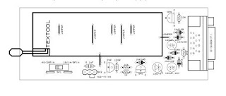
In this circuit presents a PIC programmer which program any PIC micro controller with or less 40 pin and with DIP packages.Try it.
Remember to connect according to the pin configuration i have given billow when connect PIC to ZIP socket and switch SW1 correctly when program.
Monday, February 25, 2008
Electronic thermomoter
Try this.
LCD displayed temperature is easy to concentrate.
At this thermometer, the IC thermo sensor (S8100) or the diode (1S1588) is used as the thermo sensor. When using the IC thermo sensor, the thermometry to +100°C from -40°C is possible. Also, when using the diode, the measurement to +150°C from -20°C is possible. Both sensors are contained in the kit.
This time, I used the diode as the thermo sensor to measure more than +100°C.
ICL7136 of Intersil (Harris) is used for the thermometer and is measuring the change of the forward direction minute voltages of the diode by the temperature. The 3-1/2 digits liquid crystal display (SP521PR) is used for the display. The most significant digit can display only "1".
The consumption electric power of ICL7136 is very small and it is possible to operate about 3 months continuously with the 9-V cell.
For more info